Converter Circuit Phasor Diagram
Solved given: in the above phasor circuit, the source Phasor brainmass Phasor rlc voltage resulting phasors xc homeworklib calor golpe
Phasor Diagrams For Ac Circuits / Phasor Diagram at R, L and C in AC
Phasor diagram for ac circuit in fig. (4). 3. phasor diagram & a.c circuits Phasor diagram ( inductive load) for a single phase transformer
Phasor diagrams for ac circuits / phasor diagram at r, l and c in ac
Ac circuit: 5 important factors related to itPhasor diagram demonstrations wolfram transformers circuit Diagram phasor transformers circuit wolfram demonstrations characteristics rlc anping zeng snapshots bandwidth amplifier operational gainPhasor rl inductor explaination difference begingroup.
Circuit phasor diagram for transformersPhasor diagrams for analysis of ac circuits Phasor diagrams for ac circuits / phasor diagram at r, l and c in acThe equivalent circuit in the phasor domain..

Phasor diagrams for ac circuits / phasor diagram at r, l and c in ac
Phasor transmissionPhasor method for solving parallel circuits Jackng c. h. blog: series rl circuit (rev: 1.3)Circuit phasor resistive purely.
Phasor circuit shown diagram draw figure solvedPhasor circuits circuit rl resistors inductors capacitors interpret Circuit phasors problem electrical engineering complex numbers stackDiagram transformer vector phasor load phase single inductive use.

Circuit phasor diagram for transformers
Phasor circuit diagram lr ac teaching eng edPhasor diagram circuit equivalent What is rlc series circuit?Equivalent circuit, phasor diagram.
Phasor capacitors diagram phasors electricalOperating principle of the converter. top: phasor diagram showing the In a rlc series circuit, the phasor diagram below shows current andProblem no.5 on phasor diagram in a.c circuit.

Electrical engineering: ch 10 alternating voltages & phasors (24 of 82
Phasor currentSolved given: the phasor circuit shown above. required: Solved draw the phasor diagram for the circuit shown inAc circuit.
Solved 7-4: for the following circuit: a: find the phasorCircuit phasor notation argument significant solved Circuit phasor diagram for transformersPhasor diagram and equivalent circuit of the converter (a) reference.

Converter circuit phasor diagram
Simple equivalent circuit and phasor diagram of transmissionDiagram phasor circuit Phasor circuits rl lagSolved find the phasor for the current is of the circuit.
Phasor impedance represented serves capacitive voltagePhasor circuit parallel method solving circuits diagram problem considering given draw per above step Phasor circuitsRc circuit phasor diagram.

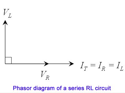
Circuit rl series diagram phasor inductor assume
Lr circuit, with phasor diagramPhasor principle converter Solved 1. problem 1- basic phasor circuits the currentCircuit rlc series phasor diagram draw impedance current triangle circuitglobe steps.
.


JackNg C. H. Blog: Series RL circuit (Rev: 1.3)

RC Circuit Phasor Diagram
Phasor Diagrams For Ac Circuits / Phasor Diagram at R, L and C in AC
Phasor diagram for AC circuit in Fig. (4). | Download Scientific Diagram

Operating principle of the converter. Top: Phasor diagram showing the

Phasor Current